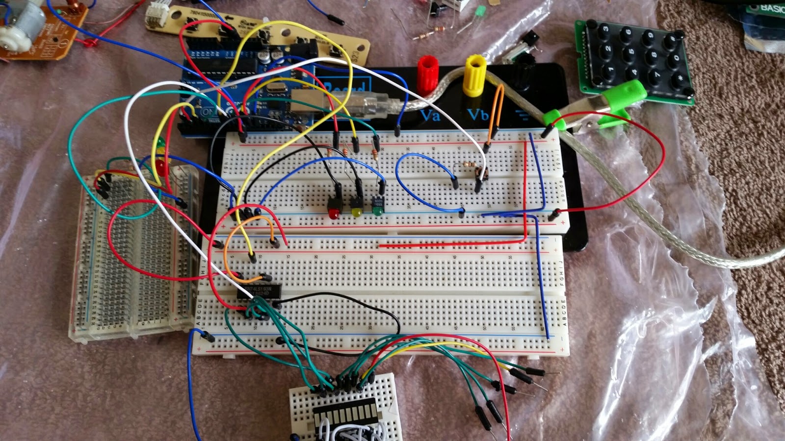
 I've got a small handful of ICs so I decided to start trying to figure some of them out. I think it was a random grab bag kinda deal from Electronic Goldmine or Mouser. I ended up with half a dozen binary counters, including a few Motorola SN74LS193Ns.
I had an idea what they did, obviously, but I've never actually read and interpreted a datasheet for anything more complicated than an LED so it took me a couple hours, and some Googling, to figure out what was going on.
It's a standard IC made by multiple manufacturers. The TI one has more information than the Motorola one but, in the end, I guess it didn't matter much. The main thing is to pain attention to the labels on the diagrams. The LS192 != LS193 so don't use the LS192 data.
TI: http://www.ti.com/lit/ds/symlink/sn54192.pdf
Motorola: https://www.physics.wisc.edu/undergrads/courses/fall2014/623/ds/74LS193.pdf
A couple things that might have been covered in the datasheets but I'm missing due to my lack of experience were found elsewhere with some Google-fu. I also wasn't sure of the Arduino Uno's duty cycle and how it would affect the counter. I did a lot of Googling and just got confused.
In the end, I stumbled on this guy's blog, which really pulled the previous stuff together. He actually uses a few of these in series to create a 12-bit counter.
1. This Bucknell course page says to put the CLEAR and LOAD pins to ground. This didn't actually work for me.
2. That course links to a lab that says something a bit different, so I'm guessing something was lost from lecture to web page in the first link. The LOAD pin is active while low, so it should be at +5V if not presetting the counter.
3. That blog explicitly shows the author using the reset pin to get started.
While the datasheet showed an example of clearing and then loading, it didn't specify exactly how to get started. Maybe these things are standard with binary counters or something...
Anyway, I was hoping to reduce my data-pin usage. I wanted the binary counter for a "pedestrian" light in emulating a traffic intersection. I'm already using six pins for the three signals in each of the two lights for the intersection.
I expected to be able to just use one pin to count up but, apparently, I need a second pin to reset the device from the get-go. At least that's what the author used in his code. Mine's the same but with a 1s delay in counting so the "pedestrian" has 15 seconds to cross:
int countup = 9;

void setup()
{
  pinMode(reset,OUTPUT);
  pinMode(countup,OUTPUT);

  digitalWrite(reset,LOW);
  digitalWrite(countup,HIGH);

  digitalWrite(reset,HIGH);
  digitalWrite(reset,LOW);
}

void loop()
{
  digitalWrite(countup,LOW);
  digitalWrite(countup,HIGH);
  delay(1000);
}
Still working on traffic signals part. The above will be set up to only work when a button is pressed. What I was hoping to do was to use the CO (carry over) pin as an input to the Arduino so when the 15s elapsed, the walk signal would be turned off and traffic would resume. Unfortunately, the carry over goes high every time the one carries over.
I'll have to play with this a bit to see how to get the walk signal's completion back to the Arduino without simply counting in the Arduino code.. I'd like to do this in hardware. I'm guessing I can learn how to use AND gates.
